|
G'day Aviators,
I hope we all have had an immaculate October month of productivity because, sadly, I have not. Progress on the plane has been slow moving in the past few weeks and I have come into a serious road block. Due to a back order of the transmitter and receiver I bought, I have yet to obtain the products I need to test my servos. Because of this, I cannot finish the wiring of the plane and ALSO have no way of testing my servos' ability to hold the weight of my control surfaces. The ailerons, rudder, and elevator cannot be added to the frame of my airplane before the electronics, so I am at a forced stopping point. HOWEVER, I have been working on the hinges of the wing's ailerons and connecting portions of the control surfaces so I will be ready when the necessary parts come in the mail. I have also been working on new ways to fasten my covering to the surface of my plane (using a promising sewing technique) and have ordered and secured a new, larger, better-fit prop to my motor. Until next time, Cap'n Louie
1 Comment
 People of the air,
G'day. It's officially time to start looking up and wearing safety goggles. As of this week, all of our wiring has been configured, all of our connections have been soldered, and all of our electronics are functional. Eights servos, our electronic speed control, our BEC, our motor, our transmitter, and our receiver have all been tested, tested, and tested again for redundancy. With new XT60 connector ends, large-diameter solder, and 5ft of 10 gauge silicon electrical wire, I wired my two batteries in series to double the voltage to 44.4 Volts and connect them, safely, to the ESC. Because that amount of voltage would ABSOLUTELY FRY any receiver I pushed through it, I also purchased a battery eliminator circuit (BEC) and added another 14.8 volt battery to our electrical circuit solely to power the receiver and the servos. Finally, to truly check the electronics, I ran up the motor to its full capacity without a prop and again with a 20" prop (securing the frame to my father's flatbed truck). *Videos of these run-ups are on the progress page for reference and they show how the transmitter ultimately sends the signal to the motor to spin. PLUS they include the best sound known to man: propellors spinning at crazy-high speeds. See you in the next blog post aviators, Capn' Louie  Fellow Airmen,
Sorry for the delayed response – we've been quite busy constructing the plane this month. As of today, I have ordered ALL of the necessary electronics for the scale airplane. These things are MASSIVE. The motor is 3" in diameter (which, for reference, can barely fit in my hand), a fistful of my esc's could regulate a CAR BATTERY, my wheels are meant to hold 80+ lbs of weight EACH, and if I had four more of my batteries I could power A WASHING MACHINE. These parts are serious, and now is where we get careful. This month, I carved out and assembled the landing gear, prepared and delivered my fellow's presentation, and bought (through the Van Eney Program) all of the materials I need to continue my project. The next step is simple: get the motor to spin. I have a TON of soldering and electrical wiring ahead of me. I have to wire the Batteries in series, connect them to the ESC, solder bullets onto the ESC and connect them to the motor, mount the motor onto the firewall of the plane, bind the receiver to the transmitter, and power the receiver using an 11.1v battery and a BEC to complete the whole configuration. The culmination of all of that work: getting one cylinder to spin around another cylinder super duper fast. After that, it's time to install the control surfaces and servos, cover the plane, and FLY. Should be easy . . . Airman, electrical engineer wannabe, landing gear designer, and professional hole-driller, Louis Lentz – Signing Off. 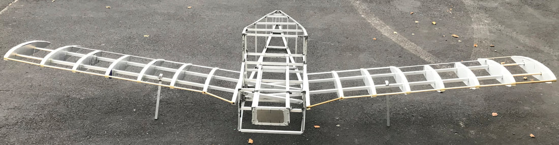 Dear Aviators,
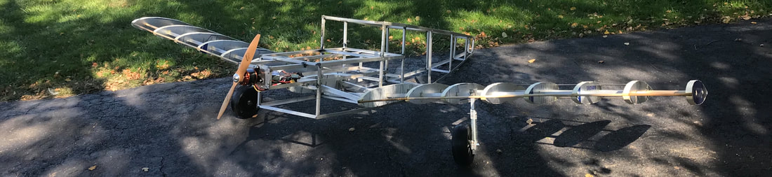
I hope you have been having a productive past few weeks, because I certainly have!! My plane, as depicted in the images above, has finally gone airborne (by a few technical inches). The landing gear bars have been secured to the spar and it is time to get rolling (literally)! Because of the heavy and expensive nature of most >6" wheels, I have decided to take an unorthodox approach to the plane's landing gear setup. I have ordered and received two 6" tonka truck wheels that weigh close to nothing and have INCREDIBLE strength (as they are designed to carry a child on their axels) and plan to use those as my plane's tires along with a significantly smaller tail wheel. I have also designed a suspension system with 70 lb max weight springs that I will be implementing to take the load off the wings upon landing. HOWEVER, none of the things mentioned above are all that exciting in comparison to this next development: HEAT WELDING. Last week I met with my out-of-school mentor, Dr. Holtgrewe, for an hour. He showed me his collection of airplane and boat models and offered a few key pieces of advice. He recommended an adhesive for the polyethylene boat film I want to cover my plane with (which sadly did not work), but also mentioned STAR HOBBY by route 50 which I sent my dad to go visit a few days ago. My dad told them about our covering conundrum and they essentially told him that there is no adhesive in the world that will work on the polyethylene material. So, after this incredible stroke of luck, I decided to put my nose to the grindstone and think of a new way of using this film. Then came the magical thing that is tin foil. Using a soldering iron at the lowest heat and a piece of tin foil, I was able to create a seam of Polyethylene by heating the substance until it just barely melted and bound with itself. As shown above, I tested this method on a 10" square of the wing and it worked GREAT!!!!! With this new technique, I will be able to full cover the plane NO PROBLEM with this incredibly strong material. As for future plans, I will be meeting with my in-school mentor to create a checklist of steps to the finalized airplane product, compiling a total budget for the plane with exact dollar amounts for the whole project, implementing the suspension system (diagrams to come later), and attaching the control surfaces to the plane. AIRMEN, ADMIRALS, AVIATORS . . . LET'S ACTUALLY GO! Louis Lentz  Aviators,
There is much to report: 1. (For research) I got into a actual Piper Warrior and flew! I gained my first flight hour and learned more about the suspension system, control surfaces, engine, propellor dynamics, and power plant of the aircraft as well. Please Checkout the Video on the Progress page for more information (and a short slideshow of "testing"). 2. The power plant of the airplane has been made!! It is the box-looking-thing on the front of the aircraft and is connected to the strongest points of the plane so that the motor does not tear off the frame. I will mount the monstrous motor to the 1/8" aluminum plate in the front and then . . . flight!!! 3. As soon as the school year starts I will purchase all of the electronics of the plane (the only parts I need left to finish it) and will wire them all preliminarily to ensure they function properly. I am sticking with the larger motor (to clarify, the largest electric motor on the market) and it should still easily get our plane in the air. 4. I am extending the wings by 9" on either side to fulfill the full 12-foot wingspan (not including the fuselage) which should give our plane lots more lift for a small addition of weight, allowing us to fly slower and better in the air. This was in response to the suspected 30+ lb weight of our plane, which will need all the lift it can get. 5. The shipment of boat covering I ordered came in last week annnnnnnndddddd . . . . . . it does not stick to ANYTHING. I have tried every glue imaginable and it simply will not work. I will bring this up with both my in and out-of-school mentors to cover the plane (I'm thinking of a solution involving rivets but my mentors will know vastly more on the subject). That's all for now! By my next blog post I will have met with my out-of-school mentor, finished securing the power plant, extended the wing, drawn plans for the suspension system of the plane, and more! Stay up there, Louis  Ladies, Gentlemen, amphibians, autotrophs, persons of all species:
It has begun. Construction on "The Big One" is underway and in full swing. In strictly following the design of the prototype, I have been able to construct the fuselage and basic structure of the wing without many surprises. Two 3/4" aluminum struts (6ft from Lowes) serve as spars for each half wing. I bought two huge pieces of insulation foam as well and used a scroll saw to cut out the precise form of each foam rib. I then used a razor blade to cut out square holes in the same position across the wing and slid the foam ribs snugly into the spars. I used epoxy to join the foam ribs and the spars permanently and attached metal and wooden stringers for support and monokote guides. I also hand cut two wing tips that add 9" to each end, sealing the official 12' wingspan, generating extra lift, and giving a truly scale look to the wings. After constructing the wings I moved on to the central wing "accepters". I used the same trigonometry as on the smaller prototype, establishing a 7 degree angle of dehydral and began brazing-rod welding the two central frame structures. Using clamps, a music stand, a blow torch, safety glasses, and a pack of 20 brazing rods, I was able to heat up 3-sided rectangle pieces of aluminum to 800 degrees. Upon contact with this heated metal the brazing rods melted and, when they cooled, they hardened forming a strong joint that I could not break by hand. I then used a type of metal-to-metal adhesive called JB Weld which, after the 24 hour cure time, gave the central wing spar acceptors tremendous strength. I slide the spars of the wings into this central structure to set the correct spacing between them and JB welded 8-foot-long aluminum "L" pieces to the bottom two corners of the frames. After they dried, I used self-tapping screws and more JB weld to attach the top two L stringers and mounted them to a smaller frame in the back. I brazing-rod welded three more frames and secured them VERY SNUGLY to the stringers to give the fuselage and empennage more strength. All of this work totaled to 15 lbs of plane and countless hours of planning, measuring, welding, glueing, drilling, test-fitting, and implementing. With the power plant, landing gear, ailerons, empennage, motor, ESC, and Battery, the total weight should be around 30 lbs. With this knowledge I researched necessary power specifications (we need a motor that can get us in the air, but that also won't add too much weight to the plane). I found a motor that carries sport planes at 28 lbs (meaning it should get our 30lb plane off the ground no problem) that weighs 44 ounces (2.75 pounds). With this motor, I will wire two batteries in series to get the necessary voltage and will create a bottom plate in the plane to hold all of the electronics. We are on a good glide slope for the project and are dangerously close to the 50% mark I designated for the end of the summer. The next steps are to contact my mentor to discuss detail-oriented aspects of the plane and possibly to design the plane in a cad software so anyone who wants to use my design to go EVEN BIGGER can do so easily. I will also move on to designing the landing gear and power plant. Stay tuned aviators, Louis Lentz signing off 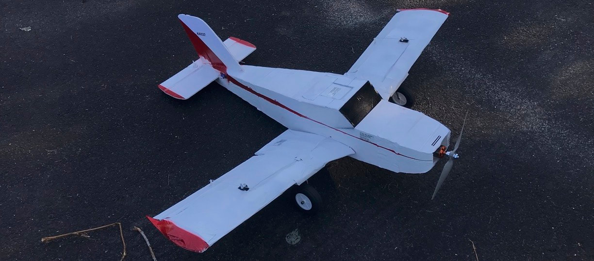 Ladies and Gentlemen,
We did it. A plane made of foam, tape, paper, plastic, and pure determination has now taken off and landed on 5 successful test flights (the videos are on the progress page for reference). After building the wing and the central dowel acceptor, the only portions left were the fuselage, power plant, and empennage. I hand cut and glued the edges of the fuselage and attached them to the central structure, secured wooden dowels to a tapered empennage to ensure the tail remained straightly aligned, slid a 5/8'' wide wooden plank to the front of the plane and bolted an electric motor to it. I wired the control surface servos to the receiver and attached the ESC (electronic speed control), and glued in control surfaces and the horizontal and vertical stabilizers to the empennage. I followed the shrunken "cheat sheet" specifications to a tee which allowed for an extremely scale looking airplane model (as seen above!!!). HOWEVER, I did not account for the fact that people are supposed to be IN THE PLANE on takeoff (of which, in my plane, there are none). This, I believe, was the reason why the CG of the airplane was so extremely aft (far back) explaining the plane's near uncontrollability on its maiden flight. Because the plane was tail heavy, it lost stability and the control surfaces were hyperactive. After moving the battery further forward, shifting the Center of Gravity forward, the plane flew far better. AND, after further adjustments to the CG and servo re-alignments, the plane began flying like a full-sized aircraft. This is not bad news. In fact, if I had discovered this later in the process (on the big plane) the altered CG would be nearly catastrophic (as our power to weight ratio would be far less forgiving). Now that I know the optimal CG of the aircraft, and all of the engineering challenges that face me in building this design, I will draw out the entire aircraft on HUGE graph paper for a final sketch before I begin building "THE BIG ONE". I have also received more information on my out-of-school mentor, and plan to setup a meeting with him in August (the earliest he is available). ALSO, before I begin construction on "THE BIG ONE", I plan to meet with my in-school mentor, Mr. Baraty, to discuss a plan of action to discuss material acquiring, flight characteristics on the larger scale, clearance to fly a 12 FOOT LONG AIRPLANE, and other details Mr. Baraty will know vastly more about than myself. That's it so far aviators. As we know, the train never stops, and Neither do I! Construction on the wing of "THE BIG ONE" is planned to be finished before August 7th, so stay tuned. Airman, designer, engineer, resident foam expert, oxygen connoisseur, and altitude lover: Louis Lentz, Signing Off  Ladies and Gentlemen,
We have hit a pivotal point in our way toward the skies. With hours of planning, glueing, and dog-petting, the wing of the prototype is finally completed. This process was far more arduous than I anticipated and took a metric TON of planning, forethought, and resourcefulness (not to mention an essential go-with-the-flow attitude). As for the time distribution, I spent around 2 hours making calculations for the plane and working from a "cheat sheet" online that reduced the measurements of a typical piper warrior to a workable, paper copy (top right photo). I then cut out the airfoil shape I needed, creating 16 ribs in total (see time lapse on the progress page). I took two 5/16 dowels we had laying around and drilled a slightly larger hole into 4 segments of a larger dowel and glued a central structure of wood together to serve as the base of the fuselage and the acceptor for the wing dowels. I then added other structural supports to the wing, and covered it in monokote (see the wing video on the progress page for more). I then attached servos, control horns, and servo wire to the wing, tested the electronics, and glued all other pieces into place to finish the wing. All-in-all, over these 15 days, I have probably put a good 25 hours into this project and spend almost all of my free time either working with the plane hands-on, or brainstorming ideas to get around new engineering challenges. Time flies when you're working on airplanes! As for future plans, it is time to begin the fuselage and empennage of the aircraft (which I will create in two separate parts and join together later). I am also still waiting to hear back from my out-of-school mentor, but plan to have met and "talked hobby" with him before next blog. I cannot wait to continue with this project, especially since the more tedious work is now behind me! Airman, Designer, Engineer, Severn Admiral, Dog petter, and hot glue expert Louis Lentz, Signing off.  Current Progress:
Ladies and Gentlemen . . . it has begun. The building of the 1/9 size prototype is underway and it will require all the materials depicted above (along with a picture of the actual plane for motivation). I have acquired and organized all of the necessary materials for my prototype including servos, foam boards, dowels, glue, transmitters, receivers, electronic speed controls, motors, propellors, and more! Next Step: The next step of this project will be to test aluminum brazing rods (shipping as we speak) for some low-heat welding practice, and to begin designing and building the center "core" of the plane out of wood and epoxy. Plans made for the future: Construction will begin at the center of the plane and will move to the power plant and wings. After I have established a strong foundation, I will build a foam fuselage body around it, glue in the vertical and horizontal stabilizers, install the control surfaces and servos, and attach the motor. In building a smaller version of the ultimate product, I will be able to identify any structural kinks without having to waste expensive materials and will be able to work through engineering challenges on a smaller, more manageable scale. When I am finished with the prototype, I plan to run a series of in-flight tests to determine the optimal center of gravity (CG), take-off speed, landing speed, battery placement, landing gear placement, power requirement, necessary bracing, ideal trim, and turning tendencies for the specific shape and weight of my design. To produce the final plane I will have to scale the 1/9 size model up by 3x, replace a few materials with stronger ones (like the wood foundation in the prototype with an aluminum foundation in the final model), and attach an absolutely gargantuan motor to the frame at the end. I will construct the prototype exactly the way I plan to construct the larger model to make sure I address as many possible engineering challenges in the smaller project before amplifying the cost, size, thrust, weight, lift, and necessary caution required in the larger model. More on July 1st, Provisional Fellow, Airman, Designer, and Engineer Louis lentz signing off |


